Circuit Diagram For Bridge Rectifier
Full wave bridge rectifier circuit working and applications Bridge river picture: bridge rectifier circuit Bridge dc power rectifier rectifiers supply case why used stack
Why bridge rectifiers are used in case of DC power supply
Full-bridge rectifier circuit diagram Bridge rectifier diagram make circuit Rectifier circuit circuits
Rectifier bridge circuit diagram phase voltage pulse output diode six rectification angle firing motor vs wave half dc current figure
Bridge rectifier diagram circuit working advantagesBridge rectifier circuit 13+ bridge rectifier schematicBridge rectifier question..
Rectifier circuit diagram wave output waveform inputWhy bridge rectifiers are used in case of dc power supply Simple bridge rectifier circuitFull wave bridge rectifier circuit diagram.

Diode rectifier 1a 50v converter bridge dc ac simple use
Circuit rectifier charger fritzing schematic rectifiersDiagram rectifier bridge wiring circuit wave applications Simple bridge rectifier circuitGeneral circuit diagram of the bridge rectifier (a) full wave bridge.
Circuit rectifier demonstrator bridge diagram seekicRectifier waveform capacitor signal resistor circuitglobe disadvantages Bridge rectifier-working diagram advantagesSimple bridge rectifier circuit.

Rectifier schematic electronics
How to make bridge rectifier circuit diagramSimple ac to dc converter the use of bridge rectifier Bridge rectifier circuitRectifier diode diodes circuitdigest.
Bridge rectifier circuit diagramBridge rectifier Bridge rectifierSimple ac to dc converter using bridge rectifier.
Rectifier circuit diagram
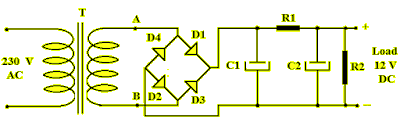
Rectifier circuit bridge simple diagram ac transformer tapped providing voltage using centerFull wave bridge rectifier Bridge rectifier demonstrator circuit diagramBridge rectifier circuit diagram with filter.
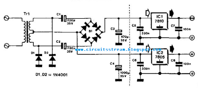
Rectifier bridge circuit wave diagram regulator icSimple bridge rectifier circuit diagram Rectifier circuit schematicCircuit rectifier bridge diagram simple.

Rectifier converter circuit
.
.

Bridge rectifier question.

Rectifier Circuit Diagram | Half Wave, Full Wave, Bridge - ETechnoG

Full Wave Bridge Rectifier Circuit Working and Applications

General circuit diagram of the Bridge rectifier (a) Full wave bridge

Full Wave Bridge Rectifier Circuit Diagram

13+ Bridge Rectifier Schematic | Robhosking Diagram

Why bridge rectifiers are used in case of DC power supply