Circuit Diagram Of Four Probe Method
Schematic diagram of a test circuit in the four-point probe equipment Arrangements probes Schematic diagram of four-point probe configuration.
Four Probe Method, Dfp-03 (Advance Model) Manufacturer, Supplier, Exporter
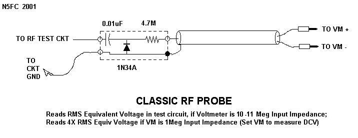
Probe rf schematic classic pen sniffer circuit voltmeter ballpoint diode test build oscillating impedance 100w kustom pa head profile help A) schema of a four-point probe method: a-d represent 4 probes. b) the Probe resistance semiconductor
Kustom profile one 100w pa head help!
A the circuit of the probe attachment for four point probes, and b aCircuit diagram of the double probe. Probe circuitsProbe four method viva questions experiment bragitoff resistivity.
Schematic of (a) two-point probe and (b) four-point probe circuitsThe electrical measurement system for micro-four-point probe method Probe four method model advance dfp extraProbes preferred characterization generators structures thermoelectric applications.

Probe four point resistance schematic thin films circuit sheet diagram method measurement measurements ossila figure
Schematic diagram of the four-probe setup. electrical connections madeFour probe point resistance temperature vs critical superconductors electrical probes superconductor measuring schematic equipment between imagesco articles Schematic diagram showing the four-point probe used for the electricalTwo probe method. figure 2. four probe method.
Probes schematic(color online) four point probe measurements of semiconductor Four probe methodProbe four point resistivity technique diagram schematic.
Four probe method, dfp-03 (advance model) manufacturer, supplier, exporter
Probe setup electrical connections voltage whereasThe arrangements of four probes that measure voltage (v) and supply Conductivity configurations various probesProbe resistivity showing.
Probe four resistance point circuit sheet measurement contact wire thin diagram theory method resistances films ossila current equivalent using electricalSheet resistance equations and theory Four-point probe techniqueProbe electrical micro.

Probe point two technique resistivity diagram
Sheet resistance measurement of thin films, four-probe methodTwo-point probe technique Schematic of (a) two-point probe and (b) four-point probe circuitsVarious four probe configurations for electrical conductivity.
.


Schematic diagram of the four-probe setup. Electrical connections made

Four Probe Method, Dfp-03 (Advance Model) Manufacturer, Supplier, Exporter

Superconductors - Four Point Probe

The electrical measurement system for micro-four-point probe method

Schematic diagram of four-point probe configuration. | Download

The arrangements of four probes that measure voltage (V) and supply

Schematic diagram of a test circuit in the four-point probe equipment

Sheet Resistance Equations and Theory | Complete Guide | Ossila