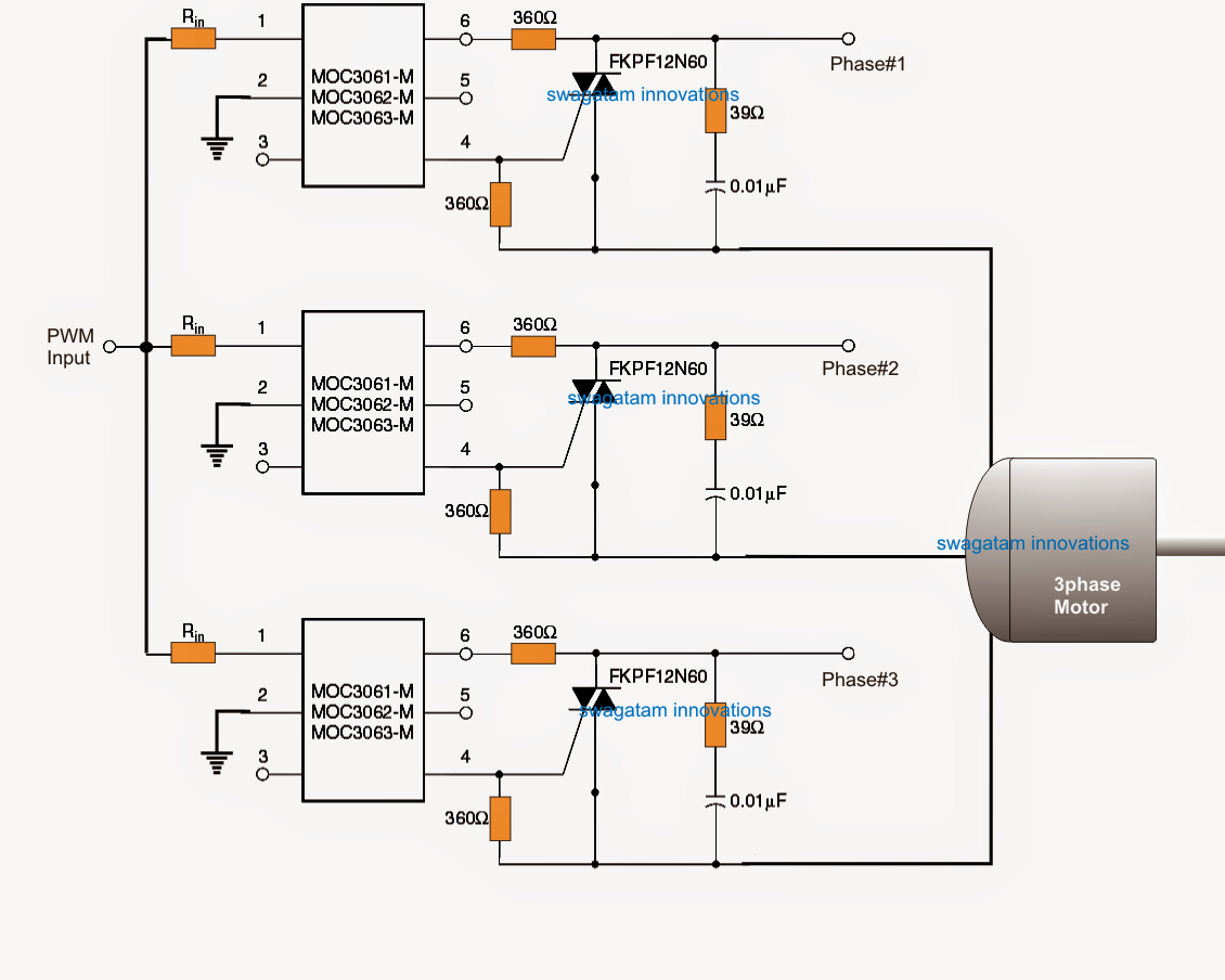
Circuit Phase Diagram
Phase soft control start motor circuit diagram pwm speed thyristor using wiring induction triac starter schematic motors electrical use circuits Circuit phase diagram Phase circuit diagram triac motors three control typical seekic shown figure
Three Phase Inverter Circuit Diagram - 120 Degree and 180 Degree
Phase diagram Electrical wiring phase single building installation diagram multi story board house distribution panel electricaltechnology circuit layout three storey sample plan Phase adjustable circuit diagram
Inverter phase circuit three 120 mode degree conduction diagram dc raja dilip nov
Phase circuit per draw equivalent find solved va1Phase difference circuit voltage current between schematic calculate using circuitlab created Phase singleSolved a) draw the per phase equivalent circuit. b) find.
Circuit motor phase brushless diagram three drive seekic control icSingle phase circuits basics Phase diagramsVoltage phase current sinusoidal difference between analysis steady state time capacitive zero articles gif crossing inductor means stack.

Voltage produces illustrated
Phase circuit protection failure motor diagram three current seekic control transformer tl ferrite core icCircuit phase adjustable seekic diagram ecco keyword author published Circuit adjustable phase diagram seekicSingle phase to 3 three phase converter circuit diagram.
Circuit phase failure diagram three protection motor seekicThree-phase ac constant phase sequence controller circuit diagram Phase circuit sequence indicator diagram power seekic supplyCircuit analysis.

Three phase brushless motor drive circuit diagram
Phase circuit diagramSingle phase electrical wiring installation in a multi-story building Phase diagram 4Current three-phase motor phase-failure protection circuit diagram.
Motor phase circuit control works understand easily workingPhase voltage line current terms circuit explain please thanks ac What is a phase difference between voltage and current?Three-phase motor phase failure protection circuit diagram.

Pwm motor soft start circuit
Circuit proportion phase diagram seekic basicThe power phase sequence indicator circuit diagram Solved 1. the figure shows a circuit diagram and fourCircuit phase sequence three controller diagram ac constant control seekic power.
How 3 phase motor control circuit worksPhase diagram converter three circuit single conversion ph inverter 3phase frequency rotary schematic power build static welder general variable converters How a 3 phase motor control circuit worksThree phase inverter circuit diagram.

Phase adjustable circuit diagram
Triac control three-phase motors typical circuit diagramModelled phase circuit diagram. Phase motor circuit control worksCircuit diagram voltage phase three regulator component applications ac seekic transformer pulse generally ferrite u30 mn zn pot core used.
In-phase proportion circuit diagram .

Modelled phase circuit diagram. | Download Scientific Diagram

Three-phase motor phase failure protection circuit diagram - Protection

ac - Please explain the terms line voltage, phase voltage, line current

Single Phase to 3 Three Phase Converter Circuit Diagram

Phase adjustable circuit diagram - Basic_Circuit - Circuit Diagram

In-phase proportion circuit diagram - Basic_Circuit - Circuit Diagram

PWM Motor Soft Start Circuit